
DIP switch

A DIP switch is a manual electric switch that is packaged with others in a group in a standard dual in-line package (DIP). The term may refer to each individual switch, or to the unit as a whole. This type of switch is designed to be used on a printed circuit board along with other electronic components and is commonly used to customize the behavior of an electronic device for specific situations.
DIP switches are an alternative to jumper blocks. Their main advantages are that they are quicker to change and there are no parts to lose.
History[edit]
US patent 3621157, filed in 1970 by Pierre Schwab,[1] is the earliest known DIP switch patent, which discloses a rotary style DIP switch.
US patent 4012608, filed in 1975 by Joseph Lockard,[2] is a DIP switch with sliding levers, the modern DIP switch.
Types[edit]
The slide, rocker, and piano types, which are very common, are arrays of simple single pole, single throw (SPST) contacts, each of which can be either on or off. This allows each switch to select a one-bit binary value. The values of all switches in the package can also be interpreted as one number. For example, seven switches offer 128 (27) combinations, allowing them to select a standard ASCII character. Eight switches offer 256 (28) combinations, which is equivalent to one byte.
A tri-state type DIP switch can be in one of three positions (+, 0, -) which allows more codes than a binary DIP switch. For example, 8 pole tri-state DIP switches offer 6,561 (38) combinations/codes compared to 8 pole binary switches' 256 (28) combinations/codes. This makes them especially suitable for encoding devices such as a remote controller.
Rotary DIP switches contain multiple electrical contacts, one of which is selected by rotating the switch to align it with a number printed on the package. Some have a knob that can be turned by fingers, or a small slot that requires a screwdriver to change them. Typically, rotary types are available in two different types of output, 1) a binary encoded output, where 10 (BCD) or 16 (hex) choices are encoded into a 4-bit binary output, or 5 to 8 choices are encoded into a 3-bit binary output. 2) a rotary version of a multipole slide switch where one signal has a choice between multiple connections, such as SPDT, SP3T, SP4T.
The DIP switch package also has socket pins or mounting leads to provide an electrical path from the switch contacts to the circuit board. Although circuits can use the electrical contacts directly, it is more common to convert them into high and low signals. In this case, the circuit board also needs interface circuitry for the DIP switch, consisting of a series of pull-up or pull-down resistors, a buffer, decode logic, and other components.[3] Typically, the device's firmware reads the DIP switches when the device is powered on.
Single in-line SIP switches are also available, which only have one row of pins instead of the two rows of pins in DIP packages. This saves on pins and space. One of the pins is a common.
With the popularization of surface-mount technology, these switches are now commonly available in non-DIP surface-mount package types. They are, however, still referred to as "DIP switches", as the term has become associated with the style of switch.
-
 Rocker DIP switch
 -
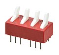
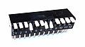 Piano DIP switch
 -
 2PST DIP switches
 -
-
 Rotary DIP switches: surface-mount (left), through-hole (right)
 -
 Rotary DIP switches (surface-mount)
 -
 Tri-State DIP switch (surface-mount)


Contacts[edit]
There are many different kinds of DIP switches. Some of the most common are the slide, rocker, piano (side), and rotary types. Slide / rocker / piano DIP switches are commonly available in 1 to 12 contacts (positions) SPST,[4][5] though some are available as special order up to 30 contacts (positions).[6]
Applications[edit]
DIP switches were used extensively in ISA architecture of PC expansion cards to select IRQs and memory addresses. Before the advent of cheaper, battery-backed RAM, DIP switches were also often used on arcade games in the 1980s and early 1990s to enter game settings such as difficulty or the number of credits per coin. DIP switches were very commonly used to set security codes on garage door openers as well as on some early cordless phones. This design, which used up to 12 switches in a group, was used to avoid RF interference from other nearby door opener remotes or other devices. Current garage door openers use rolling code systems for better security.
These types of switches were used on early video cards for early computers to facilitate compatibility with other video standards. For example, CGA cards allowed for MDA compatibility.
After the late 1990s, DIP switches became less common in consumer electronics. Reasons include the trend toward smaller products, the demand for easier configuration through software menus or plug and play, and the falling price of non-volatile memory. However, DIP switches are still widely used in industrial equipment because they are inexpensive and easy to incorporate into circuit designs, and because they allow settings to be checked at a glance without powering the system on.
DIP switches are still used in some remote controls to prevent interference; for example, to control a ceiling fan (and its light fixture) that was retrofitted to a single-circuit junction box. The DIP switches set a different radio frequency or address for each transmitter/receiver pair, so that multiple units can be installed without unintentionally controlling each other.
References[edit]
- ^ U.S. Patent 3621157.: "Miniature switch with multiple cam-operated switch contacts", filed June 1, 1970.
- ^ U.S. Patent 4012608.: "Miniature switch with substantial wiping action", filed March 25, 1975.
- ^ U.S. Patent 5010445.: "DIP switch with built-in active interfacing circuitry", filed January 25, 1990.
- ^ "DIP Switch Catalog" (PDF). C&K Switches. Archived (PDF) from the original on October 11, 2018. Retrieved October 11, 2018.
- ^ "DIP Switch Group". Tayda Electronics. Archived from the original on October 11, 2018. Retrieved October 11, 2018.
- ^ "30-position Slide DIP Switch, Part# 3-5161390-0". TE Connectivity. Archived from the original on October 11, 2018. Retrieved October 11, 2018.
External links[edit]
- DIP Switches (5MB PDF) - C&K Switches - Archive
- DIP Switches (1MB PDF) - CTS - Archive
- DIP Switches - Grayhill - Archive
- DIP Switches (33MB PDF) - TE Connectivity - Archive
- DIP Switches (7MB PDF) - Sab Switches - Archive